I. What is a floor plan drawing?
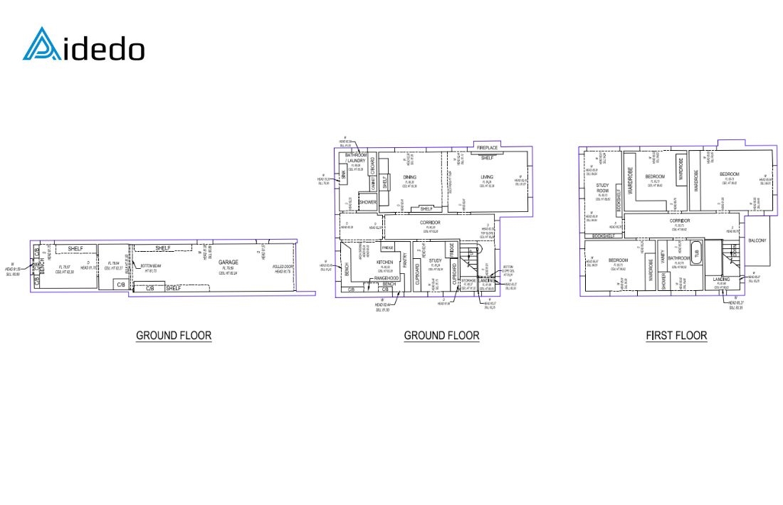
A floor plan is a 2D drawing that shows the layout of a building’s floor from a top-down view. It includes:
- Room arrangement: Locations and sizes of rooms (e.g., living room, kitchen, bathroom)
- Walls and dividers: Positions and thickness of walls or partitions
- Doors and windows: The placement, size of doors and windows
- Fixed fixtures: Elements like staircases, built-in cabinets, sinks, etc
- Dimensions and scale: Sizes and proportions to ensure accuracy
Purpose of a floor plan:
- It provides a clear view of how a building’s space is organized.
- Assists architects, engineers, and contractors in planning, construction, and inspection.
II. What is a point cloud
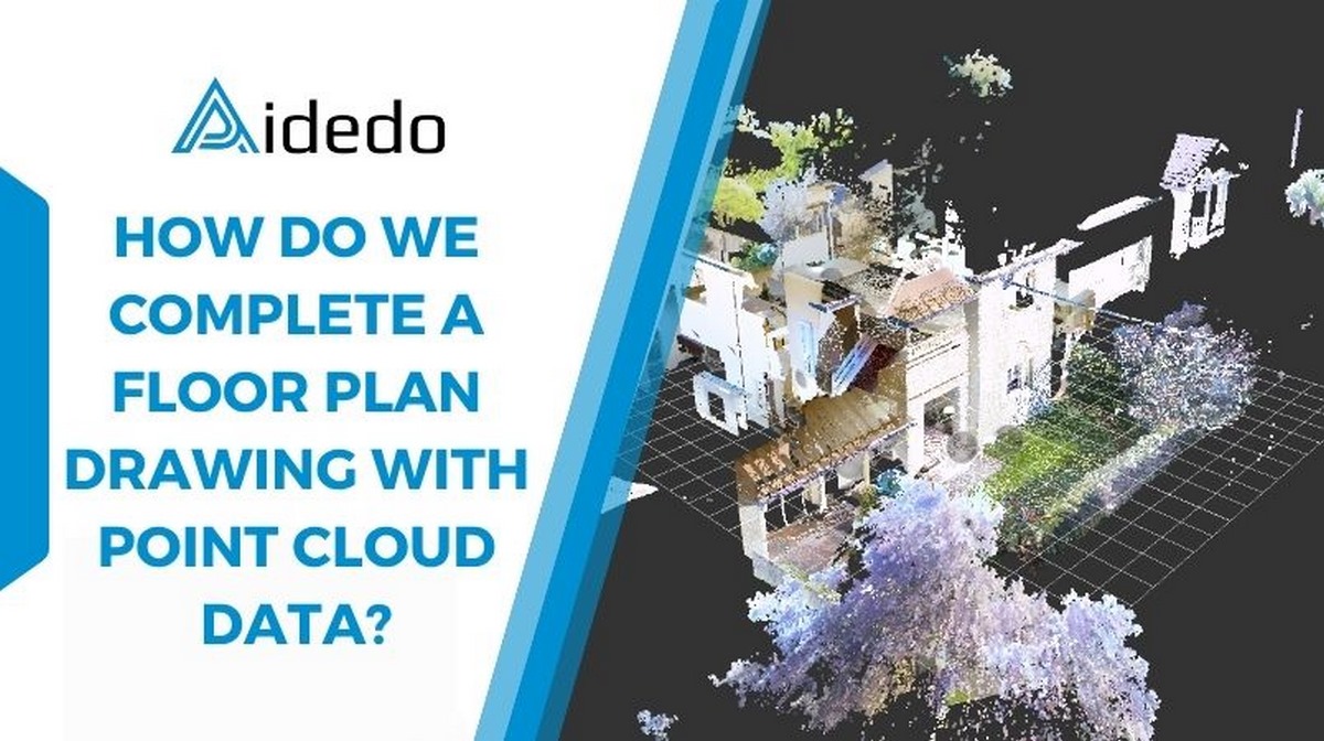
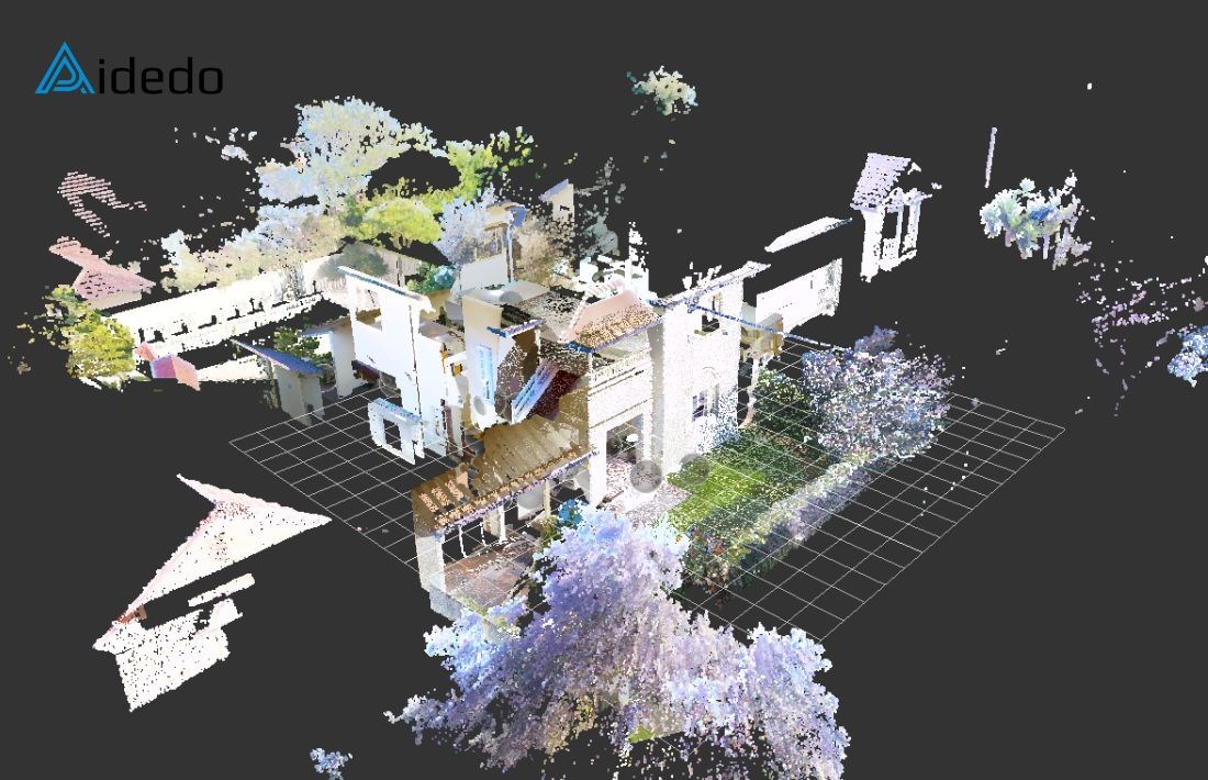
A point cloud is a set of data points in 3D space, captured using tools like laser scanners (LiDAR) or 3D cameras. Each point represents a spot on a surface with coordinates (x, y, z) and may include details like color or brightness. Point clouds are used to create 3D models of real-world objects or spaces, such as buildings or landscapes.
Common point cloud formats:
- LAS (Laser File Format): A widely used binary format developed by the American Society for Photogrammetry and Remote Sensing (ASPRS) for storing 3D point cloud data, especially from LiDAR.
- LAZ (Compressed LAS): A compressed version of the LAS format, using lossless compression.
- RCP (Autodesk Recap Project File): RCP is a proprietary file format developed by Autodesk for use with its Recap software, designed for storing and managing point cloud data. It serves as a project file that references one or more RCS (Recap Scan) files
These formats work well with common software and handle large datasets effectively.
III. Why use point cloud technology for floor plan creation?
- Accuracy: Point clouds are highly precise, reducing errors compared to manual measurements, especially for complex or uneven spaces
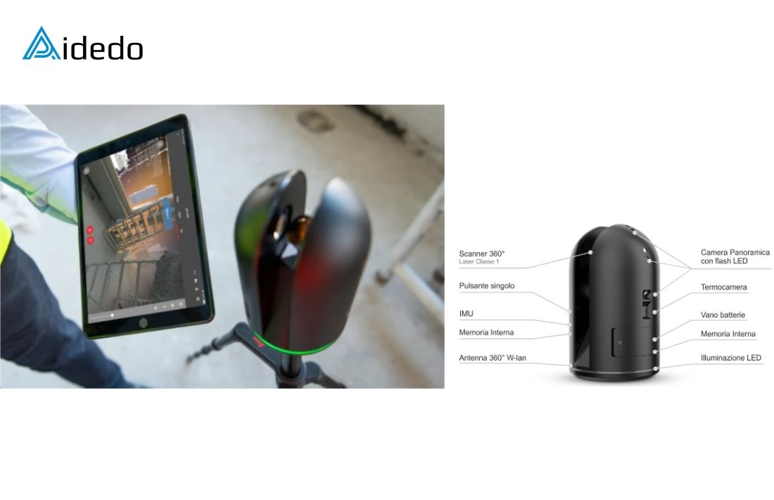
- Speed: Scanning a building with LiDAR or 3D scanners is faster than traditional methods, capturing entire rooms in minutes
Point clouds are perfect for creating floor plans that show a building’s current state, useful for renovations or property management.
However, point cloud technology requires expensive equipment, software, and skills to process the data.
Read more: land survey drafting services
IV. Workflow for creating a floor plan using point cloud data
1. Collecting and Preparing Point Cloud Data.
Scanning the Site: The client uses a 3D scanner (e.g., FARO, Leica, or Trimble) to capture the building or space. Multiple scans from different angles ensure full coverage.
Processing Data: Software like Autodesk Recap, FARO Scene, or Leica Cyclone combines the scans into a single 3D model.
Exporting Data: The point cloud is saved as an RCP file, which links to RCS files containing the scan data.
2. Receiving and Checking Point Cloud Data. (Aidedo’s role)
Receiving Data: You receive the RCP file and its related RCS files from the client.
Checking Data: Ensure all necessary files are included (a complete RCS dataset typically includes):
- RCS: The core point cloud scan file containing 3D data.
- DIFF: Differential data used for comparing scans.
- LLT: Low-level transformation data used for precise alignment of scans.
- Thumbnail: Preview images of the scan for reference
- RCC: Metadata or configuration files containing scan settings and parameters.
Verification: Use Autodesk Recap to check the point cloud for completeness, proper alignment, and accuracy, ensuring it represents the space correctly.
3. Importing the Point Cloud Data into Civil 3D
Setup: Open Autodesk Civil 3D and start a new project.
Importing: Load the RCP file using the “Attach Point Cloud” tool on the insert bar, which includes the RCS files.
Coordinate System: Set the correct coordinate system to align the point cloud with the project’s location
Display: Adjust settings (e.g., point density or color) to highlight key features like walls or floors.
4. Creating linework from Point Cloud into a Floor Plan
Creating a section: In Civil 3D, cut a horizontal slice through the point cloud at floor level (e.g., 1.5 meters high) to show walls, doors, and windows. Use the “Section Plane” tool.
Drawing Lines: Trace the point cloud to create 2D lines for walls, doors, and windows. Use polylines and Civil 3D’s snapping tools to ensure accuracy by aligning with the point cloud.
5. Finalizing and Reviewing the Floor Plan
Adding Details: Add labels, measurements, and symbols (e.g., for doors or windows) to complete the floor plan.
Checking Accuracy: Compare the floor plan to the point cloud in ReCap to ensure all features are correct and none are missing. Verify measurements and scale.
Exporting: Save the floor plan as a DWG, PDF, or other format for the client or project needs.
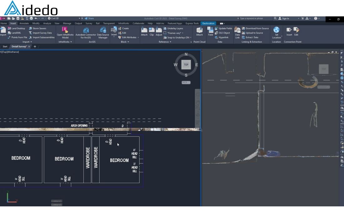
in Civil 3D software
This will be a big trend in surveying in the next few years. We know this from numbers directly from customers who use point cloud technology. The amount of work for projects using this has grown a lot in the last year. This is easy to understand because this technology helps make surveys faster and better.
To keep up with this trend, the Aidedo team always works hard to learn the software skills needed. This helps us use point cloud data well and meet high demands.
Looking to turn point cloud data into precise floor plans?
Email us at contact@aidedo.com or fill out the form below.
We’ll review your files and schedule a 1:1 online meeting to align on scope, tools, and turnaround.
Quick, accurate, and hassle-free—Aidedo helps you deliver with confidence.

