As a team specializing in technical drafting in the surveying field, we have worked on numerous Final Survey projects with various builders in the US. Our role is to support land development projects by ensuring the final drawings achieve the highest level of accuracy for certified builders or surveyors in the area.
1. What is Final Survey?
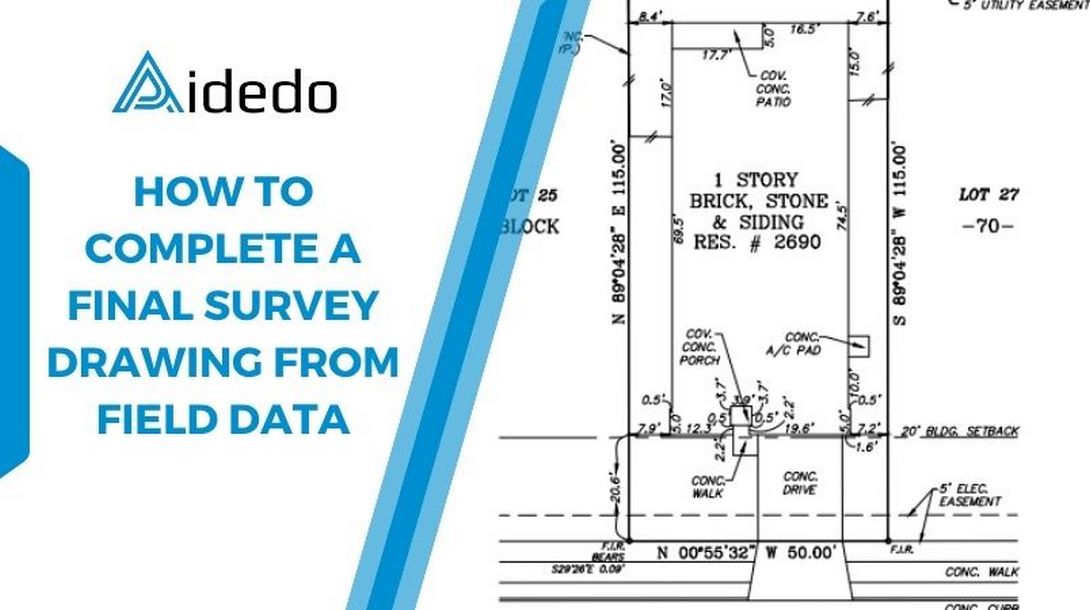
A Final Survey is a certified and detailed drawing that reflects the as-built condition of a residential lot. It includes property boundaries, all existing improvements such as the house, driveway, porch, fences, utility features, easements, setback lines, and relevant geographical information such as flood zones.
In the United States, it is a crucial legal document used during the closing process of a new home construction. It provides clear, accurate, and verifiable information about the property, helping to prevent boundary disputes, ensure compliance with zoning and building regulations, and support real estate transactions.
Unlike preliminary surveys like Form Survey or Plot Plan, the Final Survey provides the legal representation of completed construction, verified by a Registered Professional Land Surveyor (RPLS).
2. Our process for completing a final survey
Below are the steps we typically follow to complete a Final Survey project within a subdivision, ensuring every detail is accurate and meets applicable standards:
Step 1: data collection & input verification
This is a critical step. We receive raw data from the builder or surveyor, including:
- TXT file data: This contains field survey points provided by the surveyor. We import this data as the starting point for our drafting work.
- Field notes: Include coordinates, elevations, hand-drawn sketches, and detailed annotations collected directly from the field.
- Recorded Plats: Used as reference documents to verify boundaries, building setbacks, utility easements, and other lot-specific information.
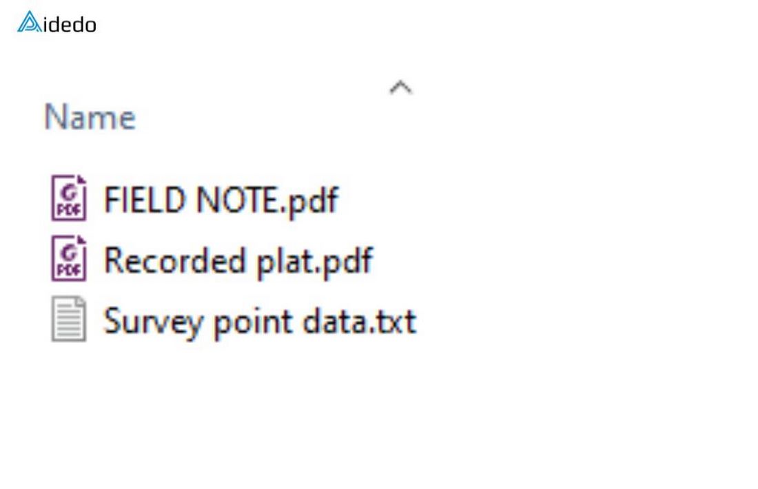
The goal of this step is to ensure that all data is complete and consistent before starting.
Step 2: Creating the project from input data
Once the data has been verified, we begin creating the drawing in CAD software (typically Autodesk Civil 3D):
- Import survey data: We import the survey points into the software
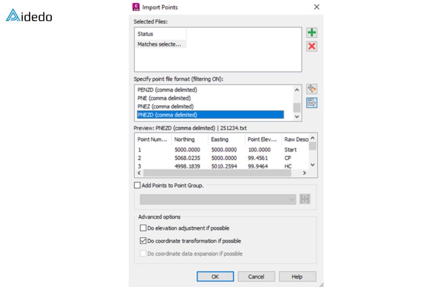
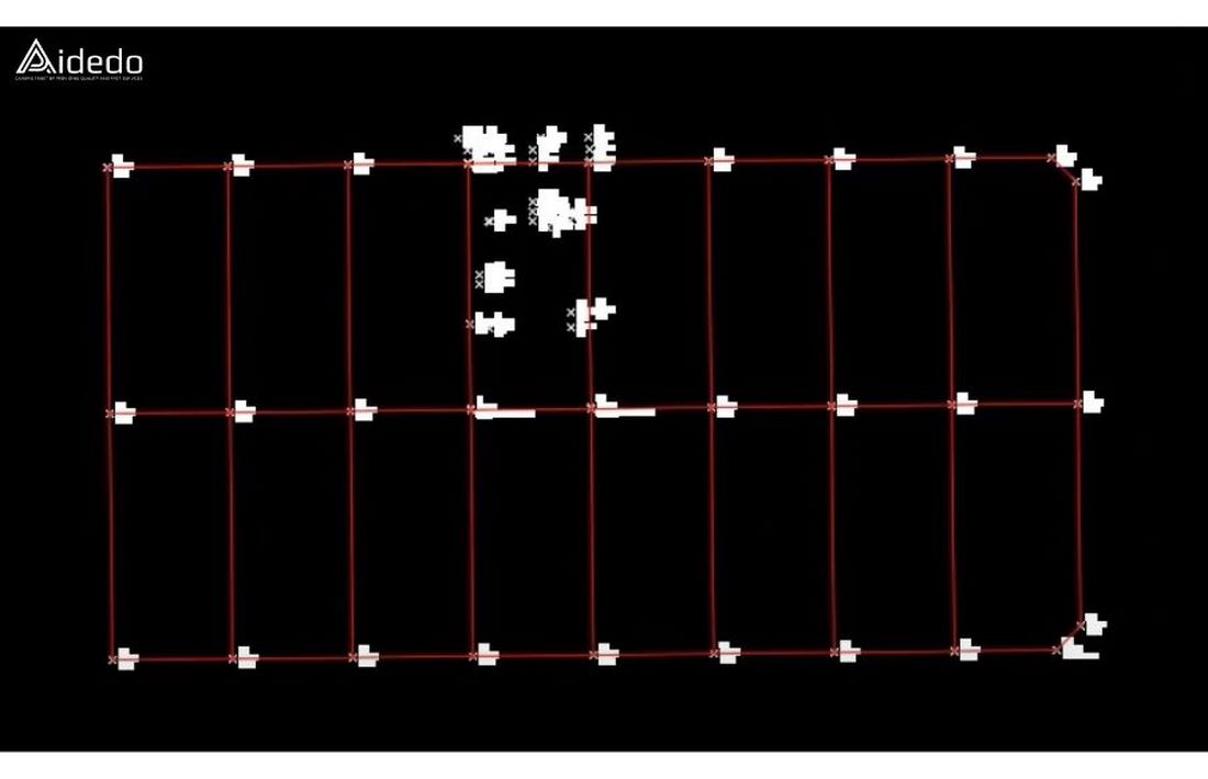
- After importing the points, we proceed to adjust the point style and label style
- We prepare all Final Survey drawings for the lots within the designated area on the plat map as requested, sometimes it’s just a few lots, other times it’s the entire subdivision. We efficiently scale our workflow whether the request involves a single lot or the entire subdivision, ensuring consistent quality across all lots
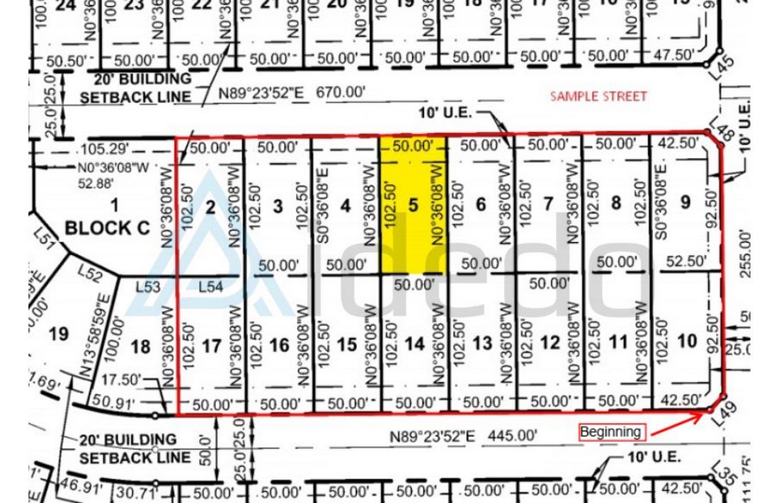
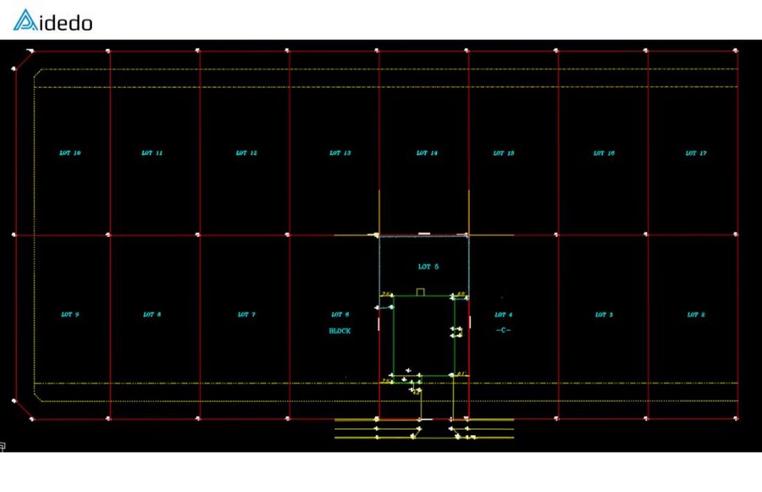
- After completing the boundary creation for all lots in the requested area, we proceed to analyze a representative lot in detail to illustrate our execution process
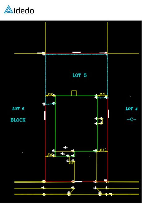
- We proceed to draft elements such as the house, concrete porch, patio, driveway, sidewalk, A/C unit, and fence based on the survey points and field notes. In addition, we include related information such as labeling property corners, annotating adjacent lots, and clearly displaying setback lines and utility easement lines.
- Next, we annotate all building dimensions, including the distances from the building corners to the property boundaries, as well as the location and size of features such as the porch, patio, and shed. We also show the distance from the fence to the main property lines, and the distance from the building to the public right-of-way line
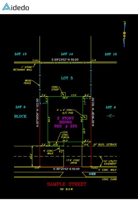
- Bearings and distances annotation: We annotate both the bearings and distances as shown on the recorded Plat and the actual measurements obtained in the field.
- Show of easements and setback lines: We draw and label utility easement lines based on information from the Title Commitment or the recorded Plat.
Step 3: Finalizing information
Once the base drawing is complete, we proceed to add other important information according to standards:
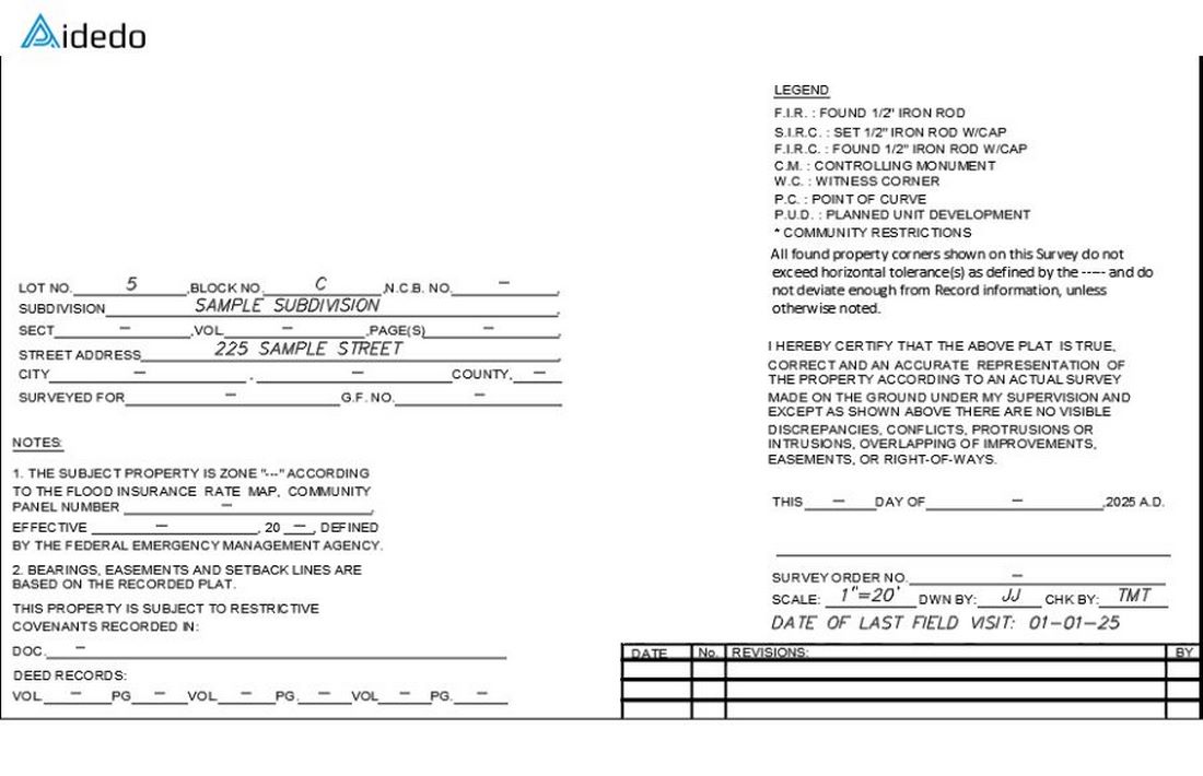
- Address and transaction information: Add the property address, lot/block number, subdivision, and section.
- Legal: Enter the legal description from the Title Commitment or the Recorded Plat.
- North arrow, drawing scale, and coordinate system: We include the north arrow for orientation, select an appropriate scale for layout clarity, and verify that the correct coordinate system (e.g., NAD83/NAVD88) is applied based on project requirements
- Legend table: We search for and include any abbreviations used in the drawing to avoid confusion and ensure clarity
- Order number and survey date: We fill in this information based on the survey request form or the surveyor’s notes from the field
- Flood zone: We identify and accurately input flood zone information on the drawing based on FEMA data, including the correct zone designation corresponding to the specific location of the lot
- RPLS Information: Allocate space for the Registered Professional Land Surveyor’s (RPLS) seal/stamp and signature
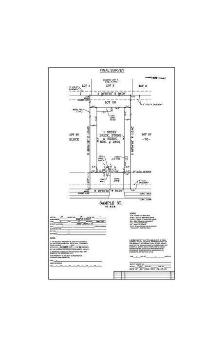
After completing all of the above steps, we produced a Final Survey drawing as requested. This serves as a representative example, and we will apply the same process to complete the remaining lots in the same manner.
Step 4: Internal Quality Control
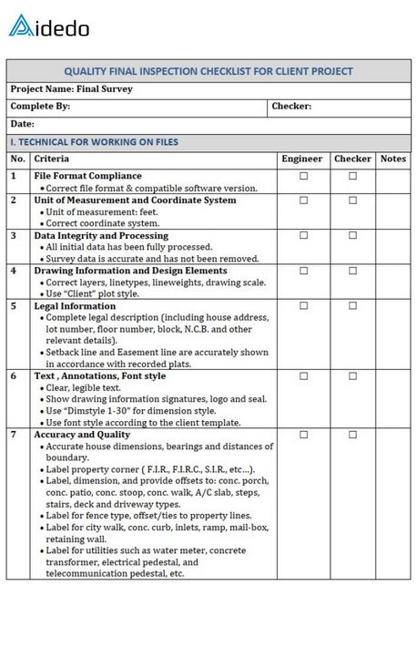
Before delivering the drawing to you, we always conduct a strict internal quality control process using a specialized checklist tailored for projects:
- Verify dimensions and bearings: Cross-check all boundary lengths and directions with the legal description or the recorded plat.
- Easement accuracy: Ensure the location and description of easements match the legal documents.
- Flood zone accuracy: Confirm that the flood zone is correctly represented according to the FEMA map.
- Verify detailed and transactional information: Check that the address, lot number, notes, and other details are complete and free of spelling errors
- Create a work checklist: This checklist is based on your specific requirements and our practical project experience. It helps ensure that every drawing delivered to you consistently meets high-quality standards
Step 5: Deliverables
We typically deliver the Final Survey in both PDF and DWG formats, with title block sized to fit 8.5”x14”, 11″x17″ or 24″x36″, based on builder requirements. DWG files are purged, audited, and compliant with builder CAD standards.
Send your project requirements to contact@aidedo.com for a direct 1-on-1 consultation and a free test to get started.
For detailed information about our services, expertise, and workflow, please visit www.aidedo.com
