What is a Set out survey?
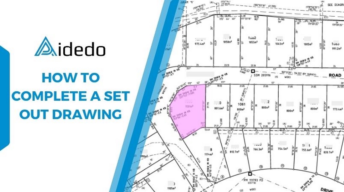
A set out survey is used to set out the exact position of a proposed structure within the legal boundaries of a piece of land.
In simple terms, a set out survey transfers the design from drawings to the real ground. For example, it marks the corners of a building on site, so that the builders can follow it during construction.
Why are they important?
- It ensures the construction is in the correct position and within the legal boundary, avoiding any disputes with neighboring properties.
- It helps the construction team work accurately and efficiently, following the design and the surveyor’s marked points on site.
- It saves costs for the owner by preventing mistakes that may require demolition or expensive corrections.
Steps to complete a set out drawing
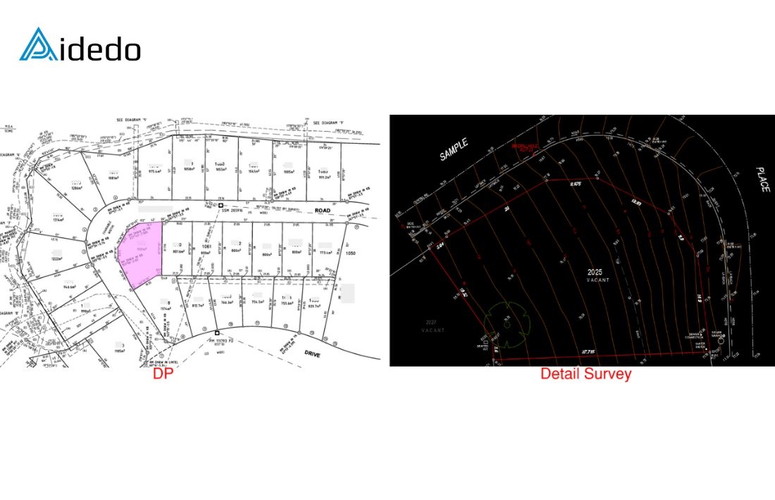
Step 1: Check the detail survey drawing provided by the client
The purpose of this step is to ensure the boundary information is accurate. In some cases, the bearing and distance in the detail survey may differ from the values shown in the DP/SP plan. If any inconsistencies are found, we will discuss them with the client immediately.
Read more: land survey drafting outsourcing services
Step 2: Set up coordinates and import survey points
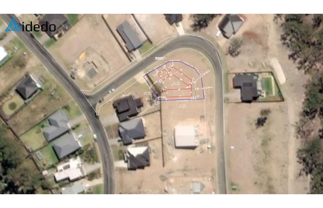
Using the site address and information from the DP/SP plan, set up the correct coordinate system in Civil 3D (for example, MGA Zone 55).
Then, check the survey data file (usually in .txt format) and import the points into the drawing.
These points represent the pegs that have been placed on site.
Step 3: Draw and label gridlines
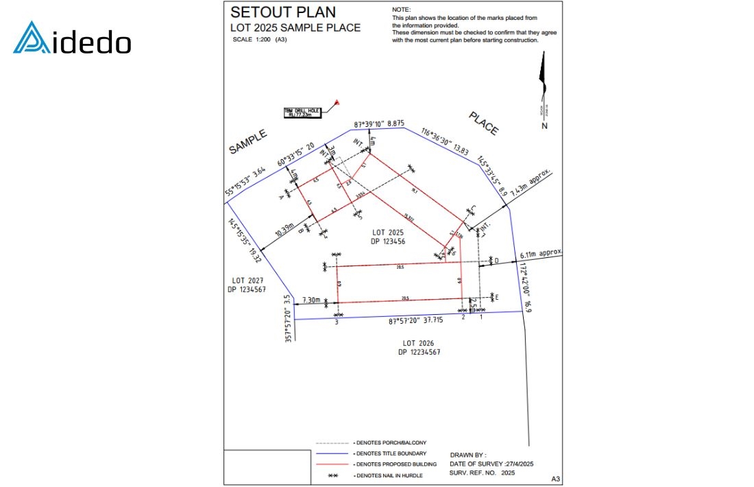
Draw gridlines across the key points on the site and assign names to each grid.
For example, use letters (A, B, C, D) for one direction and numbers (1, 2, 3, 4) for the other.
Step 4: Place key elements according to architectural and site plans
Use the architectural drawing and site plan to accurately position key elements such as building corners, infrastructure connection points, secondary structures, and so on.
Step 5: Show distances from building corners to boundaries and pegs
Clearly show the distances from the building corners to the property boundaries, as well as the distances from the pegs to the building corners.
This helps the construction team read and follow the layout accurately on site.
Step 6: Complete drawing details and annotations
Finish all remaining details on the drawing, including:
- Check setbacks and boundary clearances
- Add coordinate tables for pegs and building corners (depending on project or council requirements)
- Include symbols, labels, drawing scale, title block, and other necessary annotations.
Step 7: Final check and export files
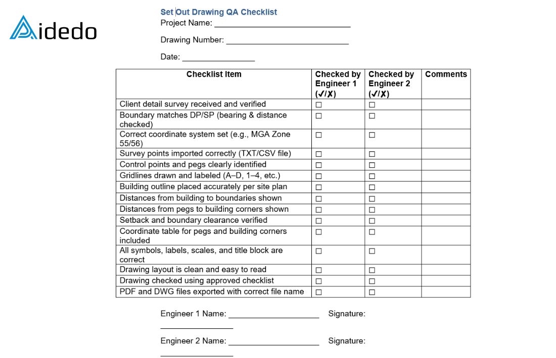
Perform a final check using the client approved checklist to ensure everything meets project requirements.
After confirmation, export the drawing to PDF and DWG formats for submission.
Contact us today via email at contact@aidedo.com or fill out the form below to receive direct consultation, detailed quotes and a FREE service trial for your first project.

