I. What is a Boundary Survey?
A boundary survey is a crucial type of land survey that determines the precise location of property lines and the monuments that mark the property corners of a parcel of land as described in a deed.
A boundary survey is conducted by licensed surveyors to establish property boundaries, resolve boundary disputes, and ensure compliance with local regulations. It is a comprehensive process that combines research, fieldwork, and analysis of existing documents to create a detailed survey plat.
During a boundary survey, experienced surveyors carefully measure and map the property, taking into account the historical records, legal descriptions, and any physical evidence on-site. They identify and verify property corners, locate boundary lines, and document relevant details such as easements, encroachments, and improvements.
II. What’s included in a boundary survey Drawing?
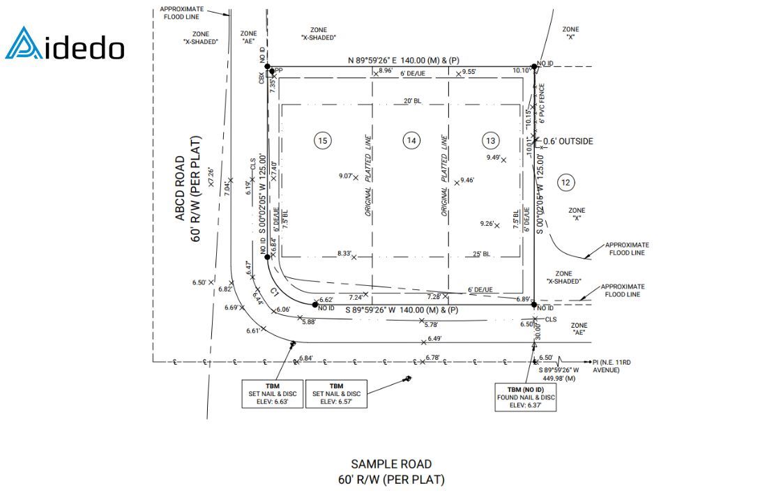
A standard boundary survey drawing typically includes:
- Address and legal description. The legal description should include the lot #, the name and section or unit number of the development as listed on the plat, the plat book number and page numbers.
- Scale bar and north arrow: the scale should be 1”=20’ or 1”=30’. The drawing should not be twisted or rotated, so the north arrow should be pointing straight up to the top of the page.
- Flood Information: For each lot, please visit https://msc.fema.gov/portal/home , enter the lot address and city/state, and click search. After that update FIRM# effective date, flood zone, BFE.
- Exact property lines (both measured and platted)
- Bearings and distances based on state coordinate systems. Typically, two bearings/distances will be shown for each property line. The measured bearing/distance will be the closest to the property line and will be indicated by (M) at the end. (This bearing/distance will, most likely, not match the Plat). The platted bearing/distance will be the furthest away from the property line and will be indicated by (P) at the end.
- Street name: Most of these plats were created decades ago, and it is not uncommon for street names to have changed since inception. If you are unsure of the street name, the county GIS website may be helpful. The street name shown on the county GIS website is usually correct
- Centerline difinition: If the centerline is straight, its bearing should match the measured bearing of the front property line, and (M) should be added to the end of the bearing/distance label. If the centerline is curved, the bearing may not match, but (M) should still be included at the end of the curve label in the curve chart (e.g., C1(M)).
- Benchmark and elevations: The field crew will locate and/or set control points in the R/W, typically either along the centerline of the street or along the edge of pavement or back of curb. In addition to the elevations shown on the lot, there should also be elevations shown for the swale in front of the lot (if present), the edge of pavement or back of curb line, and the centerline of the street.
- Property corners: The field crew will search for existing monumentation at each property corner; however, monumentation will not always be found. If a pin is found a property corner, add a “found rebar” symbol from the legend, and then add a label for the LB# or LS# of the firm or surveyor that set it (if the LB# or LS# is not included in the field shot label, add a NO ID label instead). If no pin is found at a property corner, simply add a “rebar to be set” symbol from the legend (no label needed).
- Drainage and utility structures: All drainage and utility structures located in the field should be shown and labeled.
- Fence: all fences located in the field need to be shown and labeled include material and height.
- Trees: all trees located in the field with a caliper size ≥ 12” must be shown.
Read more: boundary survey drafting service
III. Step-by- step to complete a boundary survey
The following workflow outlines the typical steps taken to complete a boundary survey for a builder service package, from initial data review to final QA and PDF submission.
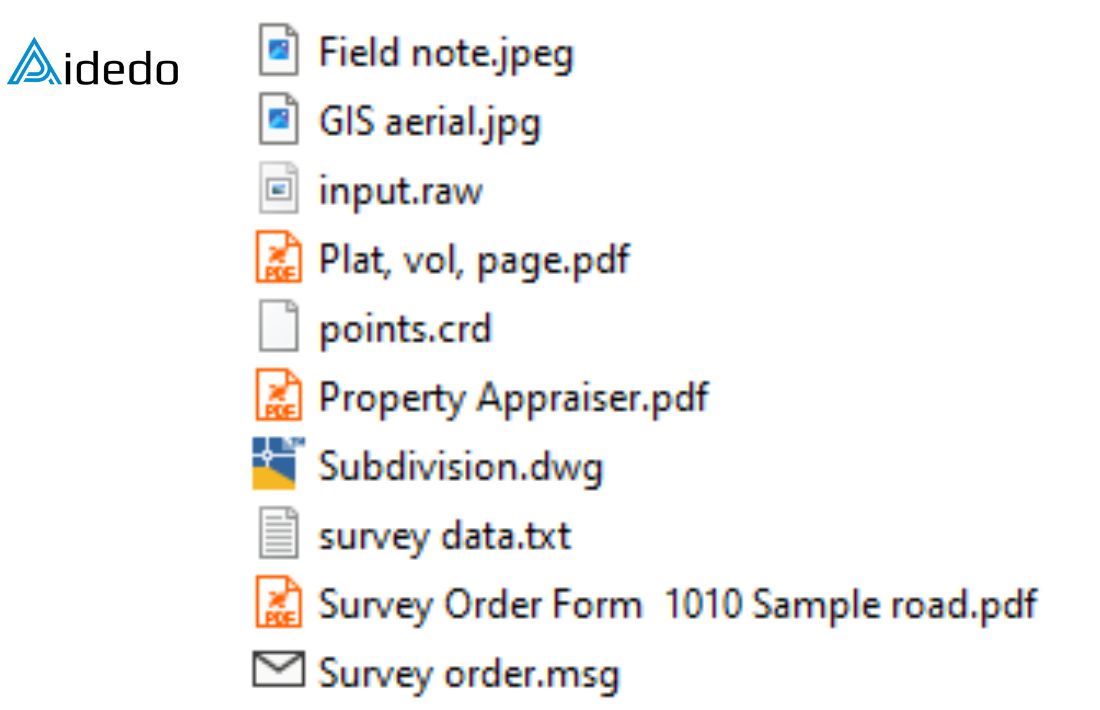
Step 1: Review all client provided data using the standard checklist
Review the checklist carefully and verify that all required documents and information have been provided, such as field notes, GIS aerial, recorded plat, subdivison CAD drawing, survey point data, …
If anything is missing, we will request the client to provide the missing items immediately.
Doing this early helps keep the project on schedule and ensures the final deliveries meet the client’s expectations for accuracy and completeness.
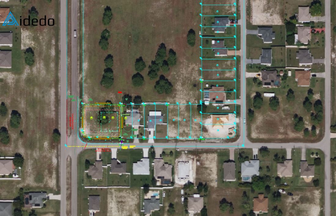
Step 2: Open the client’s subdivision CAD file in Civil 3D and import the survey point data
Use Autodesk Civil 3D to open the subdivision drawing provided by the client. Import the survey point file into the drawing. Set up the correct coordinate system in Civil 3D based on the zone indicated on the Plat (e.g., State Plane or UTM zone).
Then, verify that all imported points are displaying in the correct location to ensure the data aligns with the design base.
Step 3: Set up the appropriate viewport and scale for the subject property
Define a layout viewport that clearly displays the subject property and adjacent lots. (Common working scales are 1″ = 20′ or 1″ = 30′). It’s typical to offset the boundary of the subject property by 20 feet to include information from adjacent lots.
Based on the selected scale, adjust the text height, dimension styles, and labels to ensure clarity and consistency in the drawing.
Read more: outsourcing land survey drafting
Step 4: Add setback lines and easement lines based on the Plat
Use the recorded Plat to draw building setback lines and easement lines, as these are usually not included in the original subdivision CAD file, which typically only contains the boundary lines.
Once these lines are added, make sure to label them clearly with the correct distances and notations, following the client’s drafting standards.
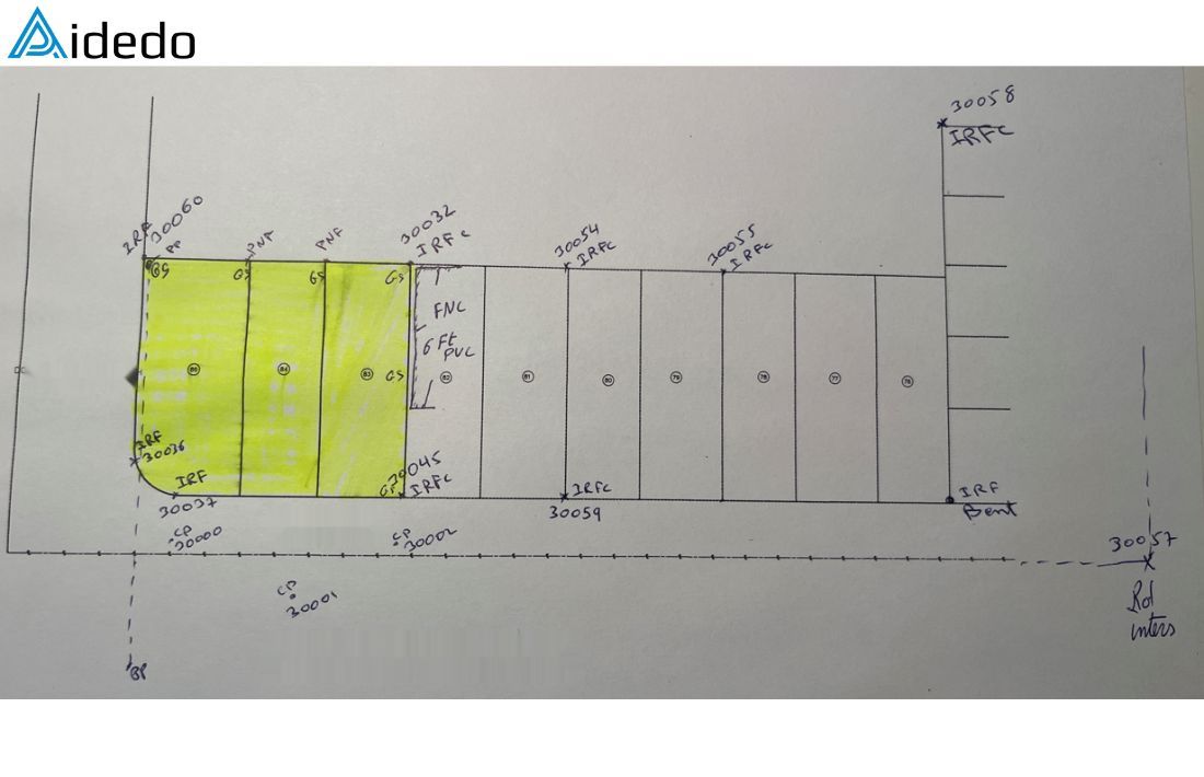
Step 5: Use point descriptions and field notes to accurately represent survey data in the CAD drawing
Use the point descriptions and field notes provided by the survey crew to accurately show all field-collected information. This may include:
- Benchmark locations
- Swales and drainage features
- Flood zone data
- Corner monumentation details (e.g., “rebar to be set”, “set ½” rebar”, “found Mag nail”, “found rebar”, etc.)
Step 6: Preview the drawing, export to PDF, and perform a final quality check before submission
Review the full drawing layout and preview all sheets.
Export the drawing to PDF format and go through the final QA checklist to catch any missing labels, incorrect linework, or formatting issues.
Make any necessary adjustments, then prepare the final file package for delivery to the client.
Ready to get started with your boundary survey?
Email us at contact@aidedo.com or fill out the form below.
We’ll review your project and get back to you within 12 hours with a detailed quote, required inputs, and turnaround time.
Before starting, we’ll schedule a 1:1 online meeting to discuss your needs, align expectations, and ensure everything is clear.
Fast. Accurate. Cost-effective.
Let Aidedo support your next project.

