This document aims to provide a comprehensive step-by-step guide for designing, calculating, and preparing the StormTech Chamber System report, ensuring compliance with project approval requirements.
As we know, the StormTech Chamber System is one of the Low Impact Development (LID) solutions categorized under Best Management Practices (BMPs). It is widely applied in projects such as stormwater treatment for parking lots, commercial, and industrial facilities. This system reduces the peak flow and volume of stormwater runoff, helping to prevent flooding, erosion, and water quality degradation downstream.
The system typically requires a retention time of 40–72 hours.
So, how do we design and accurately calculate the stormwater storage volume, develop the infiltration chart for the StormTech Chamber System, and generate the final report for submission to the relevant authorities for project approval?
Below, I will guide you through each step using HydroCAD software to perform the calculations and produce the correct report format.
Step 1. Determine Precipitation Frequency Data
Based on the information provided by the client and the project location (latitude and longitude), obtain the Precipitation Frequency Data using the NOAA Atlas 14 database.

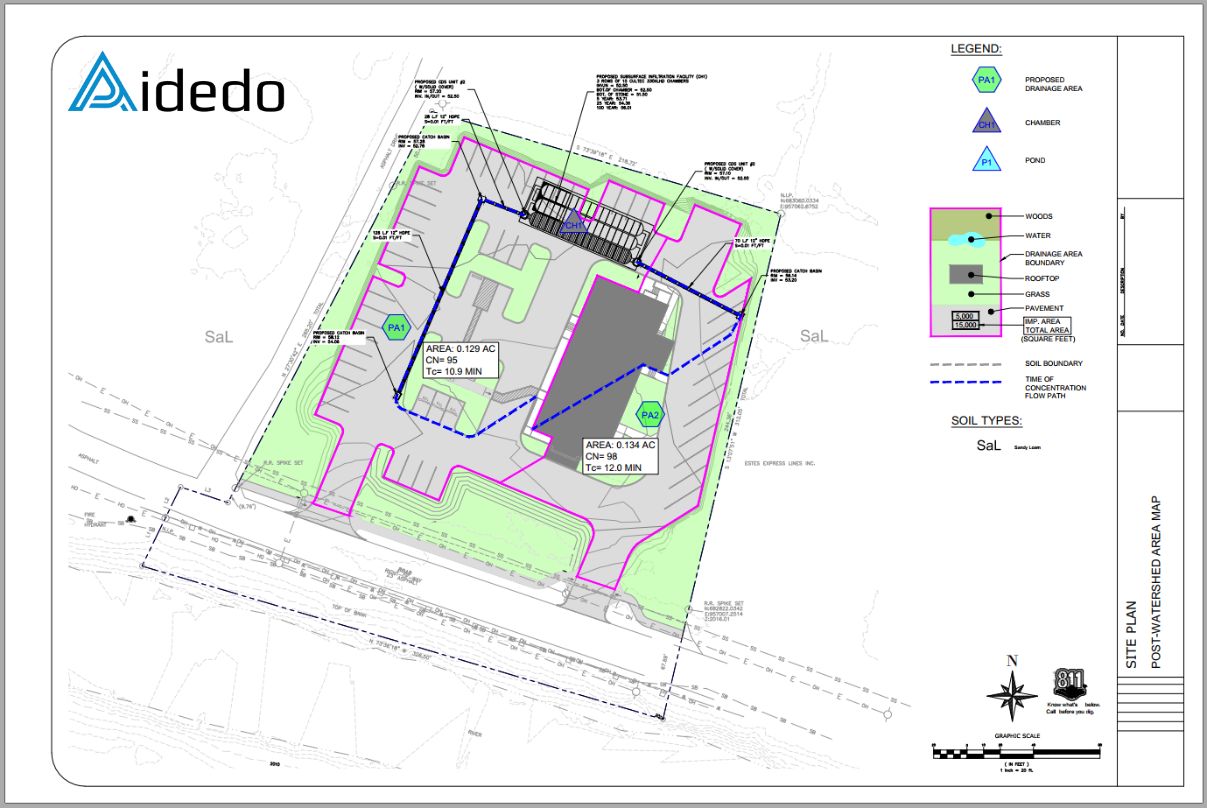
Step 2. Define Post-Development Watershed Area Map
Using the proposed site plan, identify:
- Watershed area
- Time of concentration (Tc)
- Surface material types
Simultaneously, design the stormwater collection system leading to the StormTech Chamber System. Collaborate with the client to determine the most appropriate location for chamber installation.
Read more: HOW TO DETERMINE PEAK RUNOFF USING HYDROCAD?
Step 3. Define Design Parameters for the Proposed Watershed in HydroCAD
Input the following into HydroCAD:
- Watershed Area (sq-ft)
- Curve Number (CN)
- Soil Group (e.g., Soil Group B – Sandy Loam)
- Time of Concentration (Tc), considering:
- Sheet Flow
- Shallow Concentrated Flow
- Pipe Flow
Note: Regularly review groundwater level reports to evaluate the soil’s drainage capability.

Step 4. Declare the Cultec 330XLD Chamber
Utilize HydroCAD’s built-in chamber models and ensure you update the system with the latest manufacturer product catalogs for accurate design inputs.


Read more: HOW WE ESTIMATE WORKING HOURS BEFORE STARTING A PROJECT AT AIDEDO?
Step 5. Specify the Soil Infiltration Rate
From Step 3, identify the soil group distribution and accurately determine the infiltration rate.
- Sites within Soil Groups A or B (infiltration rate > 0.5 in/hr) are suitable for the StormTech Chamber design.
- Sites within Soil Groups C or D require detailed geotechnical surveys to validate the design’s applicability.

Table: Typical Soil Infiltration Rate.
|
Texture Class |
Hydrologic Soil Group | Infiltration Rate ( inch/hour) |
|
Sand |
A |
8.00 |
|
Loamy Sand |
A |
2.00 |
|
Sandy Loam |
B |
1.00 |
|
Loam |
B |
0.50 |
|
Silt Loam |
C |
0.25 |
|
Sandy Clay Loam |
C |
0.15 |
|
Clay Loam |
D |
0.09 |
|
Silt Clay Loam |
D |
<0.09 |
| Clay | D |
<0.05 |
Source: ASCE, 1998
Read more: CIVIL ENGINEERING OUTSOURCING SERVICES
Step 6. Verify Peak Elevation at the 100-Year Storm Event
- Check the peak water surface elevation during the 100-year storm event.
- Ensure the elevation remains below the top elevation of the chamber system.
- Confirm that the system completely drains within 72 hours.

Step 7. Finalize the Report
- Prepare the final Stormwater Report according to the required submission format.
- Update input data promptly if there are any changes to the site plan or additional client requests.

Read more: WHY DO WE NEED TO REPORT DAILY PROJECT PROGRESS & QUALITY?
Let’s talk 1-on-1 with Aiden Tong – CEO & Founder of Aidedo.
You’ll get expert insights, tailored solutions, and real answers to your project needs.
Email us at: contact@aidedo.com
Or fill out the form below to book a free video consultation directly with Aiden Tong.
I respond within one to two hours, and never later than twelve hours, whether it is a weekday, weekend or holiday.

GET STARTED WITH A FREE TRIAL
Please fill out the form and we'll be in touch within 12 hours!
Related posts
HOW TO COMPLETE A FINAL SURVEY DRAWING FROM FIELD DATA
As a team specializing in technical drafting in the surveying field, we have worked on...
HOW TO COMPLETE A BOUNDARY SURVEY FOR A BUILDER SERVICES PACKAGE
I. What is a Boundary Survey? A boundary survey is a crucial type of land...
HOW DOES AIDEDO COMPLETE A TOPOGRAPHIC SURVEY DRAWING?
During the implementation of infrastructure projects, many customers ask the question: “How does Aidedo complete...
WORKSHOP: AIDEDO x AUTODESK x VIETCAD: ENHANCE INFRASTRUCTURAL DESIGN PROCESS WITH AUTODESK CIVIL 3D
On September 21, 2024, at Liberty Central Saigon Riverside Hotel (17 Ton Duc Thang Street,...
HOW TO CALCULATE GEOTECH TAKEOFF USING CARLSON SOFTWARE?
What is Geotech takeoff? Geotech Takeoff is the process of calculating the volume and area...

HOW TO CREATE A 3D SURFACE MODEL FROM SURVEY DATA
What is 3D surface modeling? 3D surface modeling is the process of creating 3D models...